
In orbital welding, the weld start position is not always just a programming parameter.
For stainless steel tube assemblies, the start position can also be selected according to the dimensional condition of the assembly after fit-up and tack welding. By placing the start position at a specific location, the local heat input and resulting weld shrinkage can be used to influence the final height, level, vertical alignment, parallelism, or angle of the assembly.
This technique does not replace proper fit-up, fixturing, or dimensional control. Instead, it can be used as a practical way to compensate for small dimensional deviations that remain after tack welding.
Why Does the Orbital Weld Start Position Affect Final Dimensions?
An orbital weld does not necessarily produce exactly the same thermal history at every point around the circumference.
The start and finish region can experience additional or overlapping heat input as the welding cycle begins, travels around the joint, and returns to the starting area. Depending on the welding program and the way the arc starts and finishes, this region can therefore experience a different thermal cycle from other parts of the weld.
Greater local heat input can result in greater local thermal contraction.
This means that the position of the start/finish region can influence where a greater amount of weld shrinkage occurs.
For tube assemblies, this effect can sometimes be used deliberately.
Instead of treating the weld start position as fixed, the position can be selected according to the deviation measured after fit-up.
Using the Start Position to Control Height and Levelness
A typical example is a flange-to-tube assembly.
After the flange and straight tube are fitted and tack welded, the flange may not be perfectly level. One side may sit slightly higher than the other.
For example:
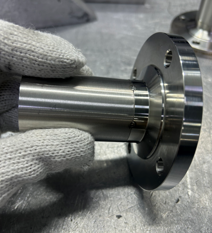
If the dimensional deviation is known before the orbital weld is started, the weld start position can be selected near the high side.
The purpose is not to “force” the flange into position mechanically. Instead, the additional thermal effect around the start/finish region can produce greater local shrinkage and influence the final position of the flange.
In this way, the start position becomes one of the process variables used to control the final dimension.
This can be useful for controlling:
- flange height
- levelness
- vertical alignment
- parallelism between components
- relative position of tube ends
The amount of correction depends on the tube size, wall thickness, joint configuration, welding parameters, restraint, tack-welding condition, and assembly geometry. It therefore needs to be established through actual process experience rather than treated as a fixed correction value.
Using the Start Position to Influence Angular Alignment
The same principle can be applied to angular deviations.
An elbow assembly provides a useful example.
After an elbow and tube are tack welded, the assembly may have a small angular deviation from the intended position.
The direction of the deviation is important.
Rather than using the same start position for every elbow weld, the start position can be selected according to the measured angular deviation.
For an elbow assembly, the back of the elbow may commonly be used as the start position under normal conditions. However, if the fit-up shows that the internal angle is too large, the start position can be moved toward the elbow’s inside area.
This increases the relative thermal effect and shrinkage in that region and can cause the assembly to move toward the desired angle.
The important point is that the start position is selected according to the actual fit-up condition, rather than simply following one fixed clock position for every joint.
The Start Position Is Not Always the Same
For production work, it is tempting to program every identical joint with exactly the same start position.
For stable and repeatable assemblies, this may be appropriate.
However, when small dimensional deviations remain after fit-up, using the same start position regardless of the actual condition can limit the ability to control the final geometry.
A more flexible approach is:
Fit-up → Tack welding → Measure → Identify deviation → Select start position → Orbital welding → Final inspection
For example:
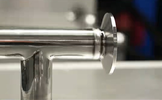
| Fit-up condition | Possible start-position strategy |
|---|---|
| One side of flange is high | Start near the high side |
| Flange levelness is off | Select the start region according to the high/low direction |
| Tube assembly has a vertical deviation | Position the start region according to the required shrinkage direction |
| Elbow angle is too large | Move the start position toward the appropriate side of the elbow |
| Elbow angle is too small | Use the opposite shrinkage direction where appropriate |
These are process-control strategies rather than universal rules. The actual result must be established for the specific joint and welding procedure.
Why Tack Welding and Fit-Up Still Matter
Using weld shrinkage to influence dimensions does not mean that poor fit-up can be corrected through orbital welding.
The initial assembly should still be properly aligned before welding.
Important factors include:
- tube squareness
- insertion depth
- joint gap
- component orientation
- tack-weld position
- fixture condition
- tube and fitting dimensional tolerance
- flange orientation
- elbow orientation
The orbital welding start position should be regarded as a fine adjustment of a controlled welding process, not as a replacement for proper assembly.
If the initial deviation is too large, changing the start position may not provide sufficient correction.
Start Position and Welding Sequence Are Related
For assemblies with multiple orbital welds, the start position is only one part of dimensional control.
The order in which different joints are welded can also affect the final geometry.
Each weld introduces localized heating and shrinkage. When several joints are present, these effects can accumulate or interact.
For example, a multi-port tube assembly may require consideration of:
- which joint is welded first
- which direction each joint tends to shrink
- where each orbital weld starts
- whether the next weld will amplify or counteract an existing deviation
- access for the welding head and clamps
- final dimensional requirements
Therefore, dimensional control of an orbital-welded assembly can involve both welding sequence and start-position selection.
Start Position as a Process-Control Variable
For automated orbital welding, parameters such as current, travel speed, pulse timing, rotation speed, and shielding gas are normally treated as process variables.
The weld start position can also be considered a process variable when dimensional control is important.
The objective is not simply to produce a visually consistent weld.
It is to achieve a repeatable final assembly.
For precision stainless steel tube assemblies, the manufacturing process can therefore be considered as:
Component preparation
→ Fit-up
→ Tack welding
→ Dimensional measurement
→ Start-position selection
→ Orbital welding
→ Final dimensional inspection
This approach is particularly useful when the final requirement involves more than weld appearance—for example, when the assembly must meet specific flange orientation, tube-end position, parallelism, or angular requirements.
The Amount of Correction Must Be Established by Process Testing
The relationship between start position and final dimensional change is not universal.
The resulting shrinkage depends on many variables, including:
- tube diameter
- wall thickness
- material
- joint design
- welding current
- travel speed
- heat input
- weld program
- start and finish characteristics
- tack-weld configuration
- fixture restraint
- surrounding geometry
- number and position of adjacent welds
For this reason, a production process should not assume that moving the start position by a certain number of degrees will always produce a specific dimensional correction.
Instead, the relationship should be established through test welds and dimensional measurement.
For example, a manufacturer may record:
Start position → initial deviation → welding parameters → final deviation
Over time, this creates a practical process reference for similar assemblies.
Orbital Welding Is More Than Controlling Weld Appearance
Orbital welding is often selected because it provides repeatable control of the welding process.
For tube assemblies, however, repeatability can also be used for dimensional control.
The weld start position provides another way to manage the predictable effects of localized heat input and weld shrinkage.
When combined with proper fit-up, tack welding, fixturing, welding sequence, and dimensional inspection, it can help control the final geometry of stainless steel tube assemblies.
The key is to treat the weld start position as part of the manufacturing process—not simply as a fixed setting in the orbital welding program.
Conclusion
The position where an orbital weld starts can influence more than the appearance of the weld.
Because the start/finish region can experience a different thermal history and localized shrinkage, its position can be selected to influence the final dimensions and orientation of a tube assembly.
For example:
- a flange-to-tube joint can use the start position to influence height or levelness;
- an elbow joint can use the start position to influence angular alignment;
- multi-joint assemblies can combine start-position selection with welding sequence to manage accumulated distortion.
The goal is not to eliminate weld distortion completely. It is to understand and use predictable weld shrinkage as one part of the dimensional-control process.
For precision stainless steel tube assemblies, fit-up, measurement, start-position selection, welding parameters, sequence, and final inspection should be considered together.
Need Orbital Welding for Stainless Steel Tubing?
If you need thin-wall stainless steel tube assemblies with orbital welding, internal argon purging, and inspection documentation, see our orbital welding service.