
A vacuum system is rarely made up of a single chamber and a pump. In practical equipment, vacuum chambers are connected to pumps, valves, gauges, manifolds, and other components, often with limited installation space and different mechanical requirements.
Rigid vacuum tubing can provide a stable connection, but it is not always the best solution when two components need some mechanical flexibility.
This is where a CF vacuum bellows can become part of the system design.
Rather than treating the bellows as an isolated component, it is more useful to consider where the bellows is installed and what role it plays between the surrounding vacuum components.
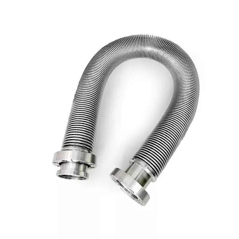
Connecting a Vacuum Pump to a Chamber
One of the common applications for vacuum bellows is the connection between a vacuum pump and a chamber.
A pump can introduce mechanical vibration into the vacuum system. A flexible bellows connection can provide mechanical decoupling between the pump and the rest of the system, depending on the bellows design and installation arrangement.
This is particularly relevant when vibration-sensitive equipment is connected to the same vacuum system.
However, the bellows should not be treated as a structural support for the pump or chamber. The surrounding equipment should have appropriate mechanical support so that the bellows is used primarily as a flexible connection rather than as a load-bearing element.
For some turbopump installations, manufacturers specifically provide vibration-damping bellows for connections where vibration isolation is required.
Connecting Two Vacuum Chambers
Two vacuum chambers may need to be connected while maintaining a controlled vacuum boundary.
A rigid connection can work when the chambers are precisely aligned and the mechanical arrangement is fixed.
In some systems, however, the chambers may experience small differences in position because of:
- Thermal expansion
- Different support structures
- Assembly tolerances
- Equipment movement
- Maintenance and reinstallation
A flexible bellows can provide a controlled degree of mechanical compliance between the chambers.
This can be useful when the two components cannot be treated as one completely rigid structure.
The bellows does not replace proper alignment. Instead, it provides flexibility where a rigid connection would otherwise transfer unnecessary mechanical stress to the flanges or surrounding equipment.
Connecting Valves to Vacuum Equipment
Valves are another common connection point in vacuum systems.
A valve may be installed between:
- A chamber and a pumping line
- Two sections of a vacuum system
- A pump and a process chamber
- A manifold and a chamber
Depending on the system layout, a bellows section can provide flexibility around the valve and simplify the connection between components.
This can be especially useful when the valve and the connected equipment have different mounting positions or when the system needs some mechanical compliance.
Vacuum equipment manufacturers commonly provide CF, ISO and other flange configurations for valves and related components, allowing them to be integrated into different vacuum architectures.
Bellows Between a Pump and a Sensitive Instrument
Not every component connected to a vacuum system has the same sensitivity to mechanical vibration.
For example, a vacuum system may include:
- Pressure gauges
- Mass spectrometers
- Analytical instruments
- Precision measurement equipment
- Motion or positioning systems
If mechanical vibration from a pump is transmitted directly through rigid tubing, it can affect components that are sensitive to vibration.
A flexible bellows can be used as part of the mechanical connection to reduce direct transmission of vibration.
The exact result depends on the bellows design, length, stiffness, mounting arrangement, and the vibration characteristics of the equipment.
Therefore, the bellows should be considered as one part of the overall mechanical design rather than as a standalone vibration-control device.
Why the Bellows Location Matters
The same bellows can behave differently depending on where it is installed.
For example, a bellows installed directly at a pump connection has a different function from one installed between two fixed chambers.
The location determines what the bellows is expected to accommodate.
Before specifying the component, it is useful to identify:
What are the two components being connected?
Which component is moving or vibrating?
Where is the mechanical support located?
Does the bellows need to accommodate movement, or is it mainly being used as a flexible connection?
What is the available installation space?
These questions are often more useful than selecting a bellows only by its flange size.
Do Not Let the Bellows Carry the Equipment Load
A common design consideration is mechanical support.
A bellows is designed to provide controlled flexibility. It should not normally be used to support the weight of a pump, valve, chamber, or long section of vacuum piping.
If excessive external loads are transferred to the bellows, the component may experience stresses beyond its intended operating condition.
A better arrangement is to provide independent support for the surrounding equipment and allow the bellows to perform its intended function as a flexible vacuum connection.
This is particularly important for larger assemblies where the connected components have significant mass.
Bellows Installation Around Valves and Pumps
The physical layout should also consider maintenance.
A vacuum system may need to be opened, serviced, or replaced during its operating life.
A properly positioned flexible section can make the connection easier to accommodate during assembly and maintenance.
For example, a bellows may be used between a fixed chamber and a pump assembly where the equipment needs to be positioned accurately without forcing a rigid tube into alignment.
However, flexibility should not be used to compensate for poor system layout.
The basic piping and equipment alignment should still be correct before the bellows is installed.
CF Flanges and System Integration
For UHV applications, CF flanges are commonly used where an all-metal sealing system is required.
A CF bellows therefore needs to be considered together with the surrounding CF components rather than as an independent tube.
The complete connection may include:
- CF chamber port
- CF valve
- CF bellows
- CF reducer or adapter
- Vacuum pump
- Instrument or gauge connection
The flange size must match the surrounding equipment, but the bellows assembly may also require specific length, internal diameter, external diameter, or mechanical characteristics.
CF bellows are available in both edge-welded and formed configurations, with different designs suited to different movement and installation requirements.
When a Custom Bellows Assembly Makes More Sense
Standard bellows are useful when the system layout matches an available configuration.
A custom assembly becomes more useful when the equipment layout requires a specific combination of:
- CF flange size
- Overall length
- Bellows diameter
- Wall thickness
- End configuration
- Installation clearance
- Movement requirements
- Leak-test requirements
For OEM vacuum equipment, the bellows can be specified as part of the original equipment layout rather than selected after the rest of the system has already been built.
This approach can reduce the need for additional adapters or unnecessary rigid sections.
What to Provide When Requesting a CF Bellows
If you are sourcing a CF vacuum bellows for equipment integration, a simple dimensional drawing is often the most useful starting point.
Ideally, provide:
| Information | Example |
|---|---|
| Application | Pump-to-chamber connection |
| CF Size | CF50 / CF100 / etc. |
| Overall Length | Required installed length |
| Material | 304 or 316L |
| Bellows ID | Required internal diameter |
| Bellows OD | Maximum available outer diameter |
| Movement | Axial or other required movement |
| Installation Space | Available clearance |
| Leak Requirement | Specified helium leak rate |
| Quantity | Required quantity |
| Drawing | CAD, PDF or dimensioned sketch |
If a replacement is required, photographs and dimensions of the existing bellows can also be useful.
Designing the Bellows as Part of the System
The most effective way to use a CF vacuum bellows is to consider it as part of the vacuum system architecture.
Instead of asking only:
“Which CF bellows fits this flange?”
consider the larger question:
“What mechanical function does this flexible connection need to perform between these two pieces of equipment?”
The answer may determine the required length, bellows structure, flange configuration, installation position, and testing requirements.
For standard vacuum equipment layouts, an available configuration may be sufficient.
For OEM systems, UHV equipment, restricted installation spaces, or unusual connection requirements, a custom CF bellows assembly may provide a more suitable solution.
Request a Custom CF Vacuum Bellows
If you have a vacuum equipment drawing, existing bellows, or simply the required CF flange sizes and installation dimensions, these details can be used to define a suitable bellows configuration.
Provide the connection dimensions, material requirements, installation space, and leak-testing requirements for quotation and technical review.
CF High Vacuum Flexible Bellows | 304/316 Stainless Steel | CF Flange Custom – WeldPure