
Yellow, brown, blue, or dark discoloration on the inside of an orbital weld is usually related to oxidation caused by inadequate internal shielding during welding.
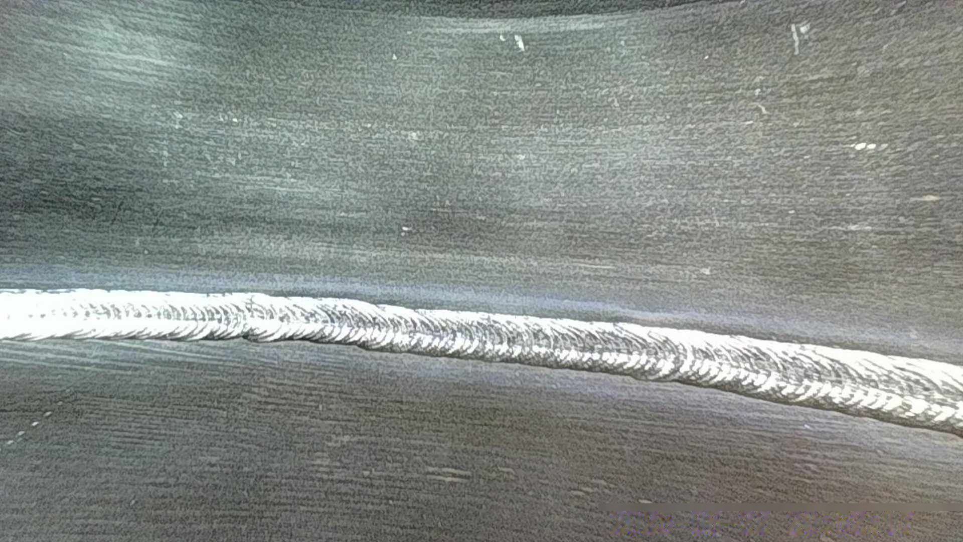
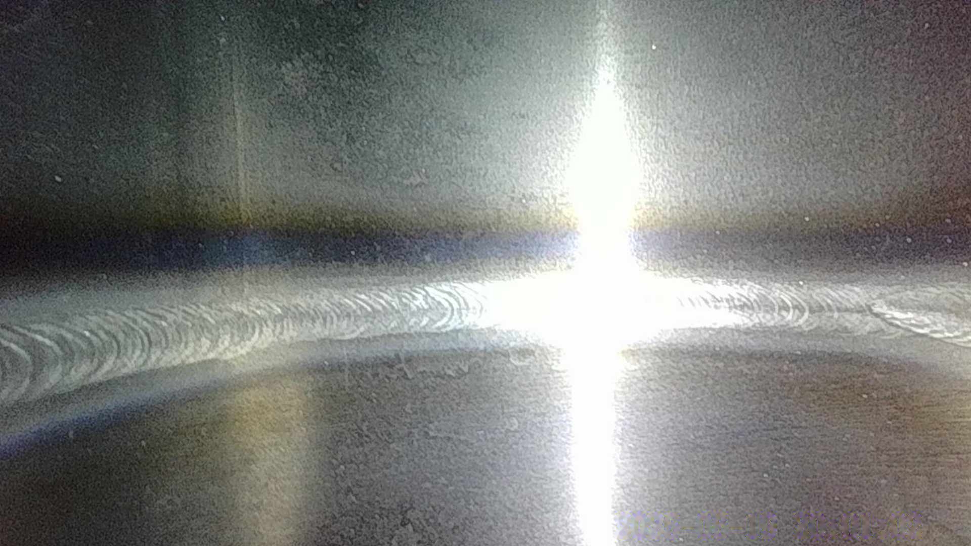
Comparison of a clean orbital weld and an oxidized weld root.
When welding stainless steel tubing, the outside of the weld may look acceptable while the inside of the tube shows yellow, brown, blue, or darker discoloration.
This is usually related to oxidation at the weld root caused by insufficient internal shielding.
For sanitary and high-purity stainless steel tubing, internal oxidation is an important welding concern because the inside surface is exposed to the process fluid. If internal discoloration occurs inconsistently, the welding machine itself may not be the only cause. The internal purge setup should also be checked.
Based on practical experience with thin-wall stainless steel tube welding, the following factors are worth checking.
1. Insufficient Pre-Purge Time
One of the most common causes of internal oxidation is starting the weld before the air inside the tube has been adequately displaced by argon.
The required purge time depends on the tube diameter, tube length, internal volume, sealing arrangement, and gas flow.
A practical approach is to establish several purge-time ranges for different tube sizes rather than using one fixed time for every joint.
For example, a workshop may use:
- At least 3 minutes for smaller or lower-volume joints
- Around 5 minutes as a common working interval
- Around 10 minutes for larger internal volumes or more difficult assemblies
These times should be treated as practical starting points rather than universal requirements. Where higher cleanliness or process control is required, measuring residual oxygen is more reliable than relying on time alone.
The important principle is:
Do not start welding simply because argon has been turned on. Allow sufficient time for the internal volume to be purged.
2. Check the Purge-Gas Hose Routing
The purge hose should allow the shielding gas to flow smoothly into the tube.
Sharp bends, excessive hose curvature, or unnecessary restrictions can affect gas flow and make the purge less consistent.
Keep the gas path as simple and unobstructed as practical.
This becomes more important when the tubing is small in diameter or the purge setup contains several fittings and hoses.
3. Check the Gas Outlet
The outlet is just as important as the inlet.
If the outlet is blocked, too small, or positioned incorrectly, the air inside the tube may not be displaced effectively.
A practical outlet diameter should provide enough gas flow to allow the internal atmosphere to be replaced while still maintaining a controlled pressure inside the tube.
For small stainless steel tube assemblies, an outlet opening of around 2 mm or larger may be used as a practical starting point, depending on the purge setup.
The exact size should not be treated as a universal specification.
Also check whether the outlet is accidentally covered by tape, a fixture, a fitting, or another component.
4. Use High-Purity Argon
The purge gas should be suitable for the welding application.
For high-purity stainless steel tube welding, 99.999% high-purity argon is commonly used.
Gas quality alone, however, does not guarantee a clean internal weld. Even high-purity argon cannot prevent oxidation if air is entering the tube or the purge system is not displacing the internal atmosphere effectively.
The complete purge system matters:
gas purity + flow + purge time + sealing + outlet configuration
5. The Direction of Purge Gas Flow Matters
The position of the gas inlet can affect how effectively the air is displaced.
As a practical approach, avoid simply introducing purge gas from the highest point and allowing it to flow downward.
A horizontal or upward gas-entry arrangement can be more effective in some tube assemblies because it can help displace the air through the outlet rather than allowing poorly purged areas to remain.
The exact arrangement depends on the geometry of the component.
The objective is not simply to fill the tube with argon. The objective is to replace the existing air inside the entire weld zone with shielding gas.
6. Do Not Insert the Inlet Tube Too Deep
The position of the purge-gas inlet can also affect the flow pattern.
If the inlet tube is inserted too deeply into a component, it can create an undesirable flow pattern or leave a region near the weld root that is not effectively purged.
For complex fittings, tees, elbows, and multi-port assemblies, the location of the gas inlet should therefore be considered together with the internal geometry.
The gas needs a clear path through the weld zone so that air can be displaced rather than trapped in a local area.
7. Check for Air Leakage
A purge system can appear to be working while still allowing air to enter through unsealed joints.
Before welding, check whether unused openings and nearby joints are adequately sealed.
For temporary workshop setups, paper tape or suitable sealing tape can be used to close other unwelded openings when appropriate.
The purpose is simple:
Argon should enter through the intended inlet and leave through the intended outlet rather than escaping through uncontrolled gaps.
Leakage becomes particularly problematic when several branches or connections are present in the same assembly.
8. The Outlet Should Not Be Excessively Large
The outlet needs to allow air to escape, but an excessively large opening can make it difficult to maintain a stable shielding environment inside the tube.
The purge system should provide enough flow to replace the internal atmosphere while maintaining a controlled positive pressure.
For example, with a purge flow of approximately 5 L/min, an outlet opening around 2.4 mm may be used in some practical setups.
This is not a universal specification. The appropriate outlet size depends on the tube geometry, purge volume, flow rate, and sealing conditions.
One simple workshop check is to verify that there is a noticeable but controlled flow of gas from the outlet.
The goal is to maintain positive pressure without creating excessive turbulence.
9. A Simple Purge-System Checklist
When internal oxidation appears unexpectedly, check the purge system before changing welding parameters.
Purge Time
- Was sufficient pre-purge time allowed?
- Is the purge time appropriate for the tube volume?
- Is the same timer being used for very different tube sizes?
Gas Supply
- Is high-purity argon being used?
- Is the gas supply stable?
- Are the hoses and fittings clean and unrestricted?
Inlet
- Is the inlet positioned correctly?
- Is it inserted too deeply?
- Is the gas path unobstructed?
Outlet
- Is the outlet blocked?
- Is the outlet excessively small?
- Is the outlet excessively large?
- Is the outlet positioned appropriately?
Sealing
- Are unused tube openings sealed?
- Are there leaks around fittings or temporary plugs?
- Is air entering through another branch?
Welding Conditions
- Is the internal purge maintained during the weld?
- Is heat input excessive?
- Has the welding speed changed?
- Has the tube size or joint configuration changed?
Why Can One Weld Be Clean While Another Turns Yellow?
This is one of the most confusing problems in stainless steel tube welding.
The welding machine may use the same programmed parameters, but the purge conditions can still be different.
For example, two joints may have the same tube diameter but different internal volumes, different fitting geometry, different sealing conditions, or different purge-hose positions.
A change in any of these factors can change how quickly the air is removed from the weld area.
Therefore, when one weld is bright and another shows yellow or darker oxidation, do not immediately assume that the welding current is the problem.
Check the purge system first.
Purging Is a System, Not Just a Gas Flow
Effective internal shielding depends on several factors working together:
High-purity argon
- adequate pre-purge time
- appropriate gas-flow path
- effective sealing
- correct inlet position
- suitable outlet
- continued shielding during welding
If one part of the system is poorly designed, increasing the gas flow alone may not solve the problem.
In some cases, excessive flow can even create turbulence and make the shielding less stable.
Conclusion
Internal yellow, brown, blue, or darker discoloration on stainless steel tube welds is often related to inadequate protection of the weld root from oxygen.
Before changing the welding current or other orbital welding parameters, inspect the complete internal purge setup.
In practical tube welding, seemingly small details—such as purge time, hose routing, outlet size, inlet position, sealing, and gas-flow direction—can have a significant effect on the internal weld appearance.
For repeatable high-purity tube welding, the purge procedure should therefore be treated as part of the welding process rather than as a secondary setup step.
Need Orbital Welding for Stainless Steel Tubing?
If you need thin-wall stainless steel tube assemblies with orbital welding, internal argon purging, and inspection documentation, see our orbital welding service.